Manufacturing in Bekasi, West Java — Indonesia ISO 9001 · IATF 16949 · ISO 14001 · ISO 45001

Pins & Spacers

Rod End Bearings

Articulated joints for linear actuators and linkage structures

Multi-directionalLinear actuatorsBionic motionLinkage structures
Rod end bearing used in a robot linkage Actuator & linkage joints · Pins & Spacers

Overview

Rod End Bearings from Actuator & linkage joints

A linear actuator pushes in a straight line, but the mechanism it drives rarely moves in one. The rod end bearing is the part that reconciles the two: it sits at the end of the push rod and allows the joint to oscillate in several directions while the actuator extends and retracts. Without it, every misalignment between the actuator axis and the load becomes a bending moment in the rod.

In a humanoid robot these bearings are the core articulated components of linear actuator push rods and linkage structures. They are what make bionic motion possible: a finger or a limb driven by a ball screw push rod needs a joint that can follow a curved path, and a rod end provides exactly that controlled multi-directional movement without introducing play.

Function

Articulated joint for linear actuators and linkage structures

Motion

Controlled multi-directional oscillation within a defined angle

Typical position

End of a ball screw push rod, or within a linkage

Housing styles

Male (external thread) and female (internal thread)

Body materials

Carbon steel, stainless steel, alloy steel

Thread

Machine thread matched to the actuator rod

Design intent

What this product solves

Six engineering decisions that separate a micro fastener that works from one that merely fits the drawing.

Reconciles actuator and load

Absorbs the angular misalignment between a linear push rod and the mechanism it drives, so the rod carries axial load instead of bending.

Controlled multi-directional movement

Permits oscillation in several directions within a defined envelope — the basis of natural, bionic articulation.

Core part of linear actuators

The standard joint at the end of a ball screw push rod, and in the linkage structures that transmit motion from it.

Removes binding from the linkage

A rigid clevis binds as soon as the geometry moves off-axis. A rod end keeps the joint free through the full stroke.

Structural, not incidental

It is a load-bearing structural part of the robot motion system, so material and thread quality are functional requirements.

Matched to the push rod

Thread size, housing style and articulation angle are specified against the actuator so the joint and the rod are designed as one assembly.

Technical data

Where rod ends sit in a robot motion chain

Reference data for design and sourcing. For a specific part, the drawing governs — these tables are the starting point for a joint review.

PositionFunctionJoint typeDesign consideration
Ball screw push rod endTransmits linear force to the limbMale rod endMust follow the limb arc through full stroke
Finger actuation linkageConverts linear motion to finger flexionMiniature rod endArticulation angle must cover full grasp range
Limb linkageCouples two moving segmentsFemale rod endLoad direction reverses each cycle
Wrist articulationAllows multi-axis movement at the wristMale or femaleCompact envelope limits housing size
Test rig and fixtureConnects actuator to test loadStandard rod endReplaceable wear part

Values are typical for the stated material and finish. Actual performance depends on the mating material, engagement length and assembly torque. Confirm with a sample test before design freeze.

Options

Heads, drives, materials and finishes

Mix these within one part number family. Where a combination is not manufacturable at your tolerance, we will say so at quotation rather than after the first lot.

Head styles

  • Male rod end — External thread into the actuator or linkage
  • Female rod end — Internal thread over a stud or rod end
  • Right-hand thread — Standard adjustment direction
  • Left-hand thread — Paired with right-hand for length adjustment

Drive types

  • Hex body (spanner)
  • Flats on housing

Materials

  • Carbon steel
  • Stainless steel
  • Alloy steel

Finishes

  • Zinc plating
  • Nickel plating
  • Black oxide
  • Passivation (stainless)

Where it is used

Typical applications

Representative positions rather than an exhaustive list. Many of our parts are designed for one specific assembly and never appear in a catalogue.

Application reference by assembly position
Assembly Typical use
Humanoid limb actuator Joint between the ball screw push rod and the limb segment
Dexterous finger drive Miniature rod end converting tendon or push-rod travel into flexion
Parallel linkage Two rod ends keeping a platform level through the stroke
Wrist articulation Articulated joint allowing multi-axis movement at the wrist
Exoskeleton frame Compliant joint between actuator and limb brace
Test fixture Replaceable articulated joint in a fatigue rig

Quality control

What we measure on every lot

Inspection is not a final gate. It is a set of checks placed where a process can actually drift, with the result recorded against the lot code.

01

Thread gauge, GO / NO-GO

02

Articulation angle and freedom of movement

03

Housing dimensions against drawing

04

Material certificate per lot

05

Surface finish and plating thickness

06

Visual inspection for cracks at the housing

07

Assembly torque where supplied as a set

Questions

About rod ends

The questions our engineers answer most often on this product family.

Still deciding? Send the assembly drawing and the service condition. We will recommend a size, finish and locking method — and tell you if a different product family is the better answer.
When is a rod end needed instead of a clevis?
Whenever the actuator axis and the load path are not perfectly aligned through the stroke. A clevis only rotates in one plane; a rod end allows multi-directional movement, which is what a curved limb path requires.
How is the articulation angle specified?
From the mechanism geometry: the angle between the actuator axis and the load axis at each end of the stroke. Give us the stroke and the mounting points and the required angle follows from the drawing.
Do you supply rod ends with the push rod?
Rod ends can be supplied together with the matching threaded push rod so that thread engagement and joint alignment are specified as one assembly rather than two separate purchases.
What decides the material?
Load and duty cycle. Carbon steel with plating covers most actuator joints; stainless is used where corrosion or clean-environment requirements apply; alloy steel where the joint is highly loaded.

Related products

Often specified together

These families are frequently used in the same assembly, or as an alternative when the joint requirement changes.

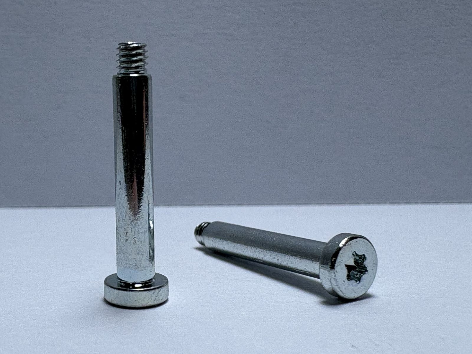
Shoulder screws with precision ground shanks

Pins & Spacers · Pivot & locating duties

Shoulder Screws & Pins

Shoulder screws and precision pins for joints and motion structures — a ground shank that acts as a pivot or locating shaft while the thread clamps the assembly together.

Connection + locationRotation supportRobot joints
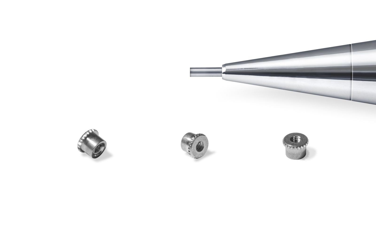
Threaded inserts for plastic and light alloy assemblies

Thread & Panel · Light alloy & plastic

Thread Inserts

Thread inserts give a lightweight structure a thread that survives repeated assembly — wire thread inserts, self-tapping inserts and key-locking inserts for plastic, aluminium and magnesium.

Wire · self-tapping · key-lockingBrass / steel / titaniumRepeated assembly
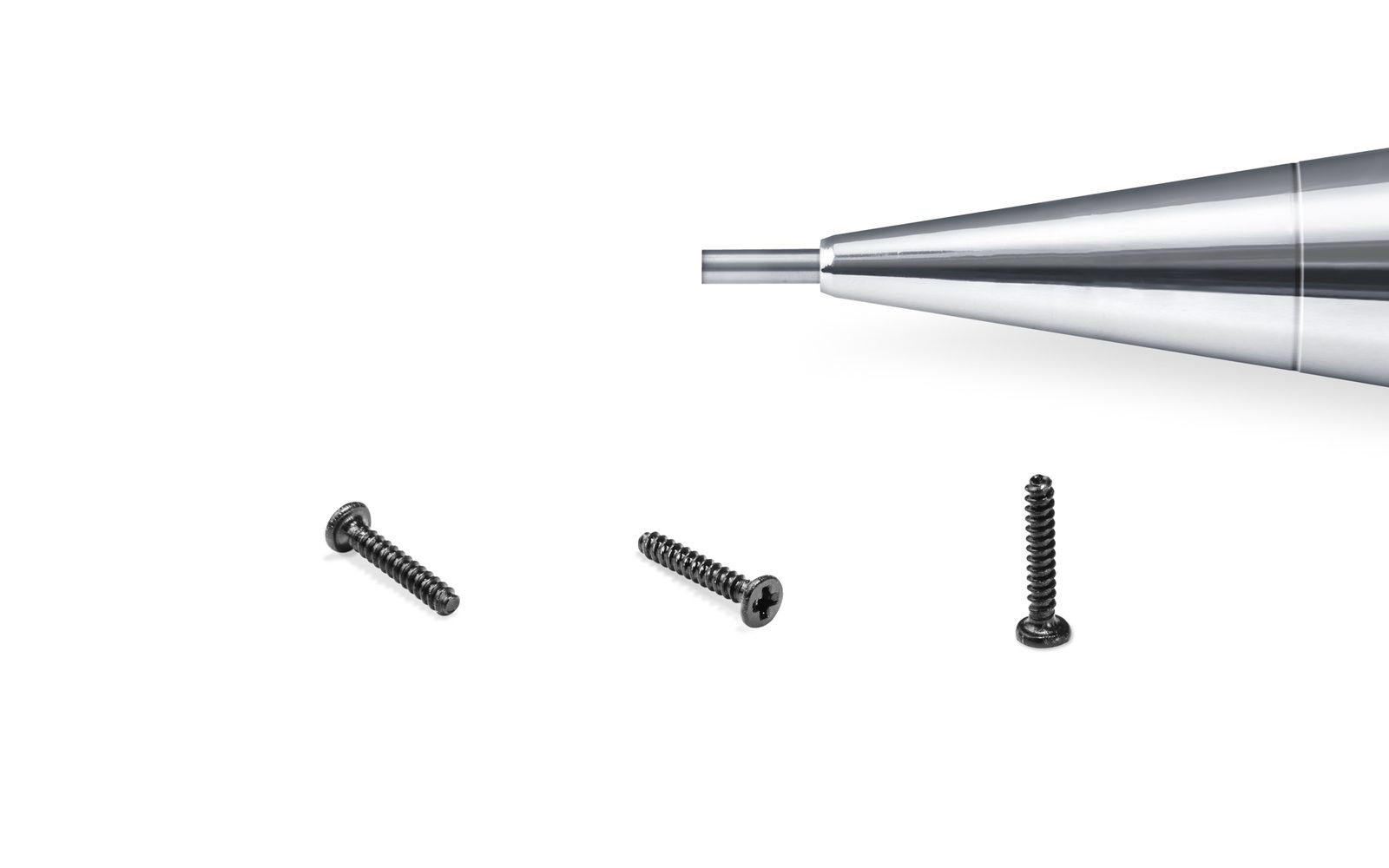
M0.8 machine thread micro screws beside a pencil tip for scale

Micro Screws · M0.6 – M2

Machine Thread Micro Screws

Micro machine screws that engage a pre-formed thread — a tapped hole, a brass insert or a heat-set nut — and hold their clamp load through repeated disassembly.

Coarse & fine pitchRepeated re-assemblyStainless / carbon steel

Need rod ends to your drawing?

Send a drawing or 3D model with the mating material and finish requirement. The reply is a process route, a tolerance review and a price — with the assumptions stated.