Manufacturing in Bekasi, West Java — Indonesia ISO 9001 · IATF 16949 · ISO 14001 · ISO 45001

Product range

Precision fasteners for millimetre-scale assemblies

Fourteen product families covering the fastening, locating and spacing needs of miniature assemblies — made on one site in Bekasi, Indonesia, with the process chain behind them.

M0.6 – M2 catalogue14 product familiesPVD in-houseLot-level documentation

01 · Product family

Micro Screws

Threaded fasteners from M0.6 to M2, with or without a pre-applied locking element.

4 products

M0.8 machine thread micro screws beside a pencil tip for scale

Micro Screws · M0.6 – M2

Machine Thread Micro Screws

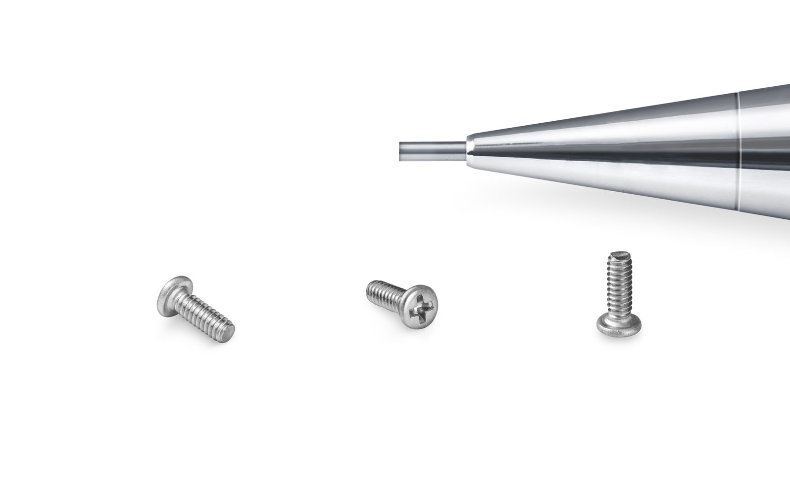
Micro machine screws that engage a pre-formed thread — a tapped hole, a brass insert or a heat-set nut — and hold their clamp load through repeated disassembly.

Coarse & fine pitchRepeated re-assemblyStainless / carbon steel
Pan head self-tapping micro screws arranged in a row

Micro Screws · M1.0 – M2.0

Self-Tapping Micro Screws

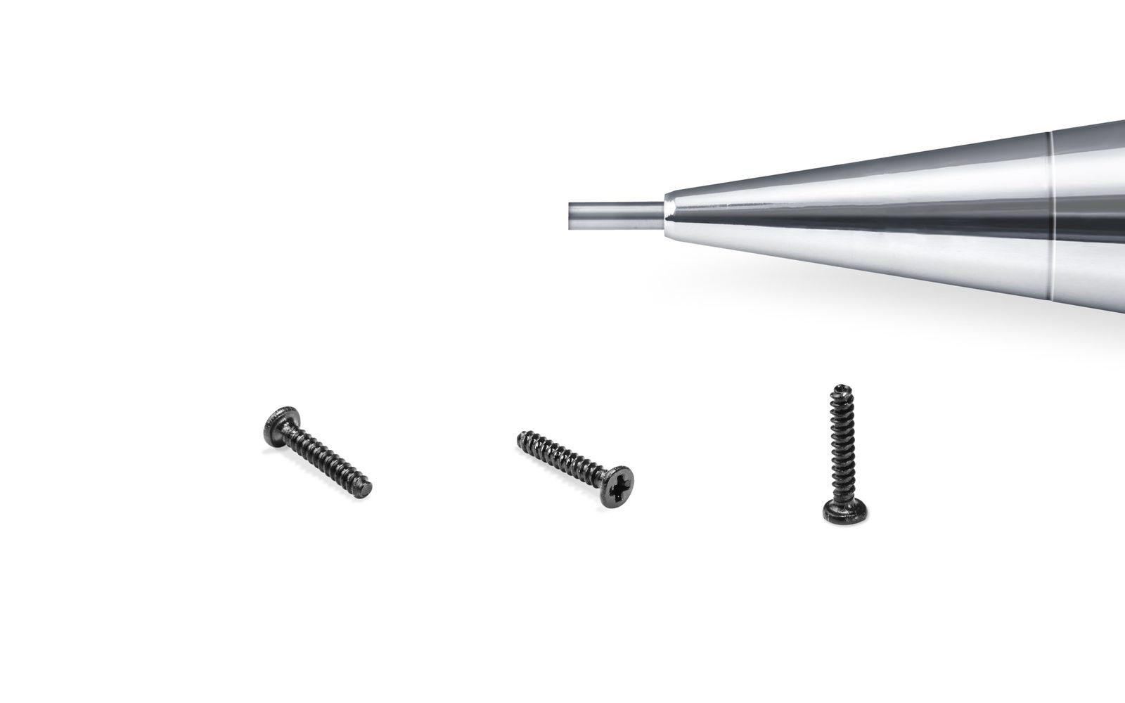
Self-tapping micro screws remove the tapping operation: the screw forms its own thread in a plain pilot hole in plastic or thin metal, so the housing needs no insert.

No insert requiredPlastic & sheet metalCase hardened
PVD coated screws with a CD-pattern decorative finish

Micro Screws · M1.0 – M2.0

PVD Coated Screws

Physical vapour deposition puts a dense ceramic film on the screw in a vacuum chamber — hard enough to resist driver wear, thin enough that it does not close the thread or change the fit.

Vacuum depositedTen colour optionsNo hydrogen embrittlement
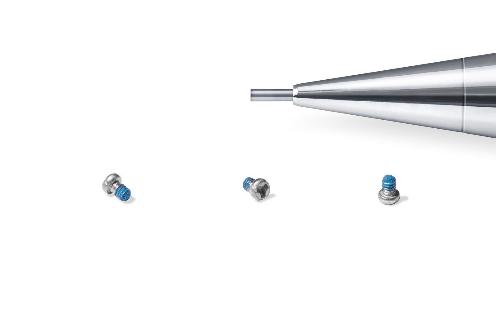
Micro screws with a blue pre-applied threadlocking element

Micro Screws · From M0.8 × 1.0 mm

Precoated Screws

Screws supplied with a locking, sealing or vibration-damping element already applied — micro-encapsulated adhesive, nylon patch, sealant or damping coating, from M0.8 upward.

Four product families90°–360° coverageExternal or internal thread

02 · Product family

Precision Components

Ground pins, standoffs, inserts and captive assemblies that locate and space as well as clamp.

0 products

03 · Product family

Specialties

Stamped parts and security drives for assemblies that need more than a standard fastener.

0 products

Geometry reference

Head profiles and drive types

The head sets the stack height and the bearing area; the drive sets the torque you can transmit and the cam-out risk on the line. Both should be chosen together.

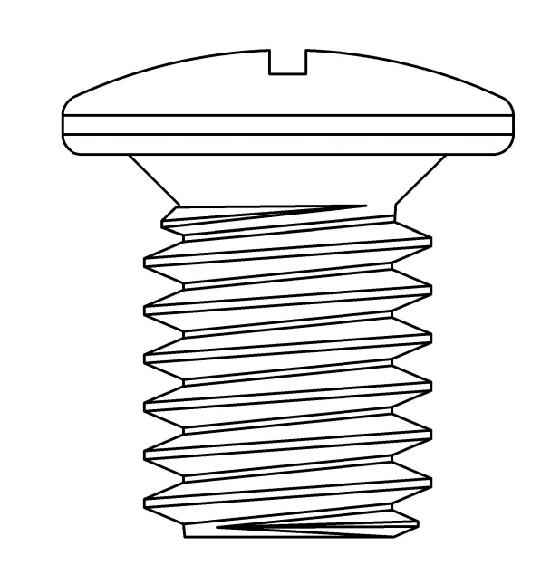
Pan head screw profile drawing

Pan head

Rounded top with a flat bearing face. The default for general assembly because it gives the largest bearing area under the head.

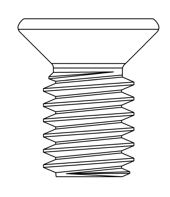
Countersunk head screw profile drawing

Countersunk head

Seats flush in a 90° or 120° countersink. Requires a matching countersink in the mating part; the head carries load on a conical face.

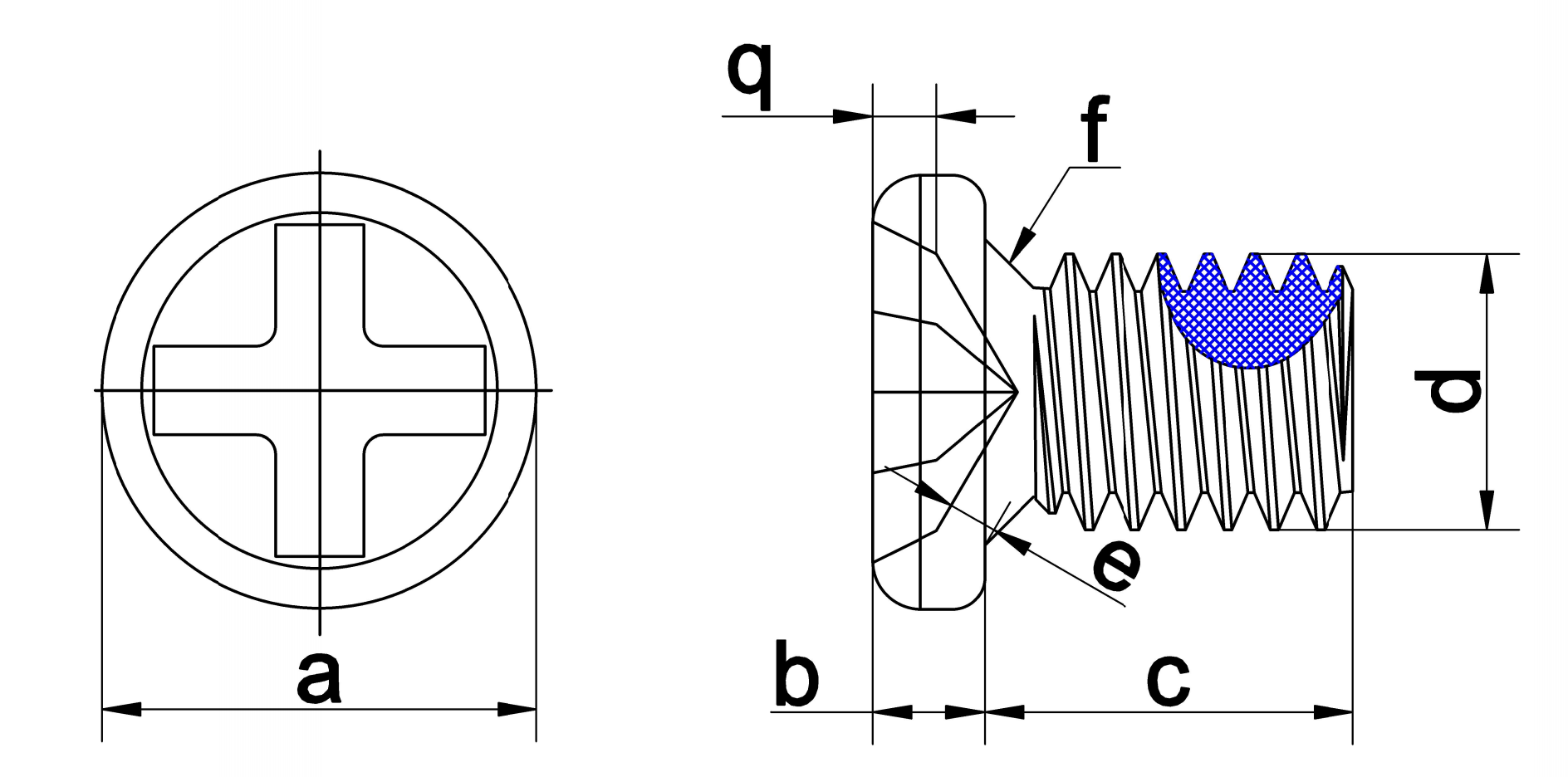
Countersunk screw dimensional reference drawing

Dimensioning

Length is measured from the bearing face, not the point, for flat and pan heads. For countersunk screws it is measured over the complete head.

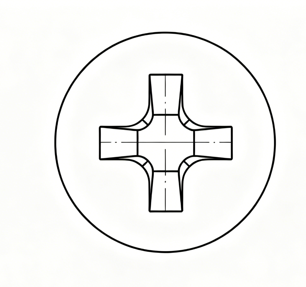
Phillips cross drive recess diagram

Phillips

Self-centring and cheap, with deliberate cam-out at high torque. Still the most common drive in consumer electronics below M2.

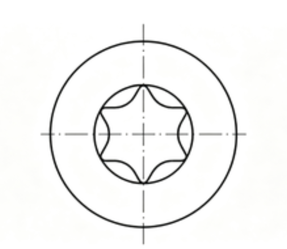
Torx six-lobe drive recess diagram

Torx

Six-lobe geometry transmits more torque with less cam-out. Preferred for high-cycle automated lines and for security variants.

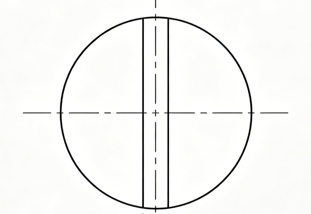
Slotted drive recess diagram

Slotted

The only practical drive below M0.6, where a cross recess cannot be formed reliably. Low torque transfer, but simple and tool-tolerant.

Materials

Material selection by environment

Strength, corrosion and weight trade against each other. The right answer depends on the mating part, the cleaning chemistry and the service life — not on a preference for stainless.

GradeCorrosionStrengthWeightTypical finishBest for
SWRCH10APoor without coatingLowMediumZinc, zinc-nickelHigh-volume small parts, easiest to form
SWRCH18APoor without coatingMediumMediumZinc, zinc-nickelGeneral micro screws, heat treated where needed
SWRCH22APoor without coatingMedium-highMediumZinc, zinc-nickelParts that need strength after quench and temper
SUS302HQGoodMediumMediumPassivationCold-formed stainless, the grade for a clean head
SUS304Good in normal atmospheresMediumMediumPassivation, PVDGeneral electronics and housings
SUS316Best against chloridesMediumMediumPassivation, PVDCoastal, medical, chemical exposure
SUS410ModerateHigh when hardenedMediumPassivation, PVDSelf-tapping screws, wear parts
TA2 (titanium)ExcellentMediumLightestPassivation, anodiseWeight-critical, non-magnetic joints

These are the grades documented in the catalogue. Corrosion ratings assume the stated finish — stainless in a chloride environment can still pit, and bare carbon steel rusts within days.

Finishes

Finish selection by requirement

Finish is a specification, not a colour. It sets corrosion life, friction coefficient and appearance — and it changes thread dimensions.

FinishThicknessSalt sprayFriction (µ)AppearanceNotes
Zinc trivalent5 – 12 µm96 – 240 h0.18 – 0.25Blue / clearEconomic default for steel
Zinc-nickel8 – 15 µm480 – 720 h0.15 – 0.20Silver / blackAutomotive and outdoor
Electroless nickel3 – 8 µm240 – 480 h0.18 – 0.22Bright silverUniform on complex geometry
Black oxide1 – 2 µm24 – 72 h (oiled)0.20 – 0.28BlackCosmetic internal parts
Dacromet / Geomet8 – 12 µm720 – 1,000 h0.14 – 0.18Grey-silverHighest corrosion, no hydrogen risk
TiN PVD2 – 4 µm96 – 240 h*0.20GoldWear resistance, decorative
CrN PVD2 – 5 µm96 – 480 h*0.22Silver-greyCorrosion plus wear
DLC2 – 3 µm96 – 240 h*0.10Near-blackLow friction, black cosmetic

* PVD salt spray figures assume an interlayer. PVD alone is a wear and appearance coating, not a sacrificial corrosion barrier. Values describe each system in general; the figure committed to a drawing is the one measured on the part.

Thread fit warning: a 10 µm coating adds up to 20 µm diametrally. For Class 6f fits, specify gauging after coating or thread masking. The drawing tolerance does not automatically cover the coating.

Size reference

Metric coarse thread and tapping data

Thread data for the documented catalogue range. Fine pitch and left-hand threads are a tooling question rather than a catalogue question — send the drawing.

SizeCoarse pitch (mm)Tapping drill (mm)Close fit hole (mm)
M0.60.150.450.55
M0.80.200.650.75
M1.00.250.750.85
M1.20.250.951.05
M1.40.301.101.20
M1.60.351.251.35
M2.00.401.601.70

Tapping drill values are practical starting points targeting roughly 75% engagement in steel. Aluminium usually takes a slightly smaller drill, and plastics are specified by body diameter rather than thread. Full thread data sits in the thread standards reference.

Not sure which family?

Start from the joint, not the catalogue

Three questions usually narrow the choice to one or two families.

01

Is the mating part metal or plastic?

Metal thread means a machine screw. Plastic means a thread-forming screw, or a machine screw with an insert if the joint will be opened more than a few times.

02

Does the fastener also locate something?

If it acts as a pivot or aligns two parts, you need a ground shoulder screw or a dowel pin — a standard screw with a loose clearance hole will not hold position.

03

Will the joint be opened in service?

Serviceable joints need a nylon patch or a captive design. Permanent joints can use encapsulated adhesive, which holds better but cannot be re-used.

Direct support

Send the assembly drawing

We will tell you which family fits, which tolerance is driving cost, and whether a different joint would be cheaper. No obligation, and no sales engineer in between.

Typical reply time

Direct from engineering

Ten families. One plant. One tolerance standard.

Whether you need 10,000 M1.2 screws or a custom stamped contact, the same engineering and quality process applies.