Technical reference
Head & drive types
The head sets the stack height and bearing area. The drive sets the torque you can transmit and the cam-out risk on the line. Both should be chosen together, early.
Head profiles
Six head geometries
Every profile is a trade between height, bearing area and flush appearance. At micro sizes the height difference between two profiles can be a fifth of the available stack.
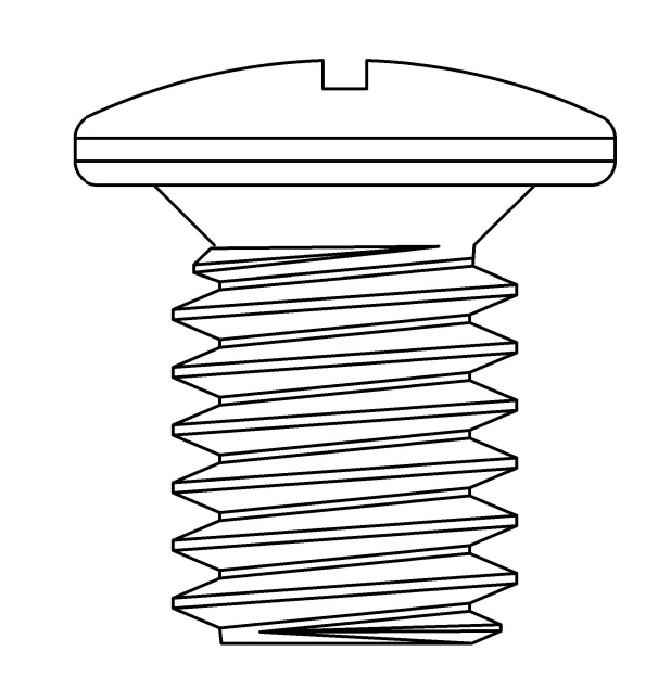
Pan head
Rounded top with a flat bearing face. The default for general assembly because it offers the largest bearing area under the head for a given diameter.
Typical use
General electronics, plastic housings, board hardware
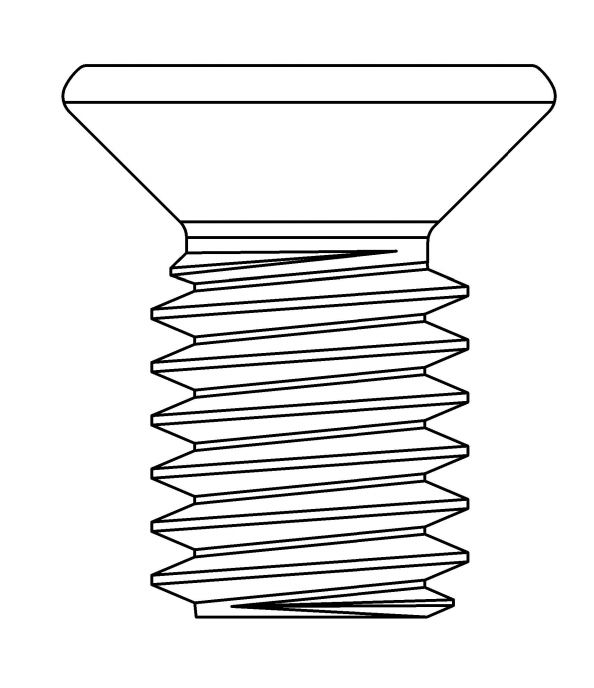
Countersunk (flat) head
Conical underside seats flush in a matching 90° or 120° countersink. Load is carried on the cone, so the mating part must be countersunk to match.
Typical use
Flush cosmetic panels, hinges, covers
Wafer / low profile head
A shallow version of the pan head, down to 0.35 mm height. Recovers stack height in camera modules and other tightly packed assemblies.
Typical use
Camera modules, wearables, thin device stacks
Cheese / fillister head
Tall cylindrical head with a deep drive recess. The height allows a deeper recess, which transmits torque more reliably at very small sizes.
Typical use
Instrumentation, adjustment screws, deep recesses
Binding head
Similar to a pan head but with an undercut beneath the head, allowing it to bind two thin parts or clamp a wire without a separate washer.
Typical use
Wire clamping, thin panels, two-part binding
Hex washer head
Hexagon head with an integrated washer face, spreading load over a larger area. Driven with a socket or spanner rather than a recessed drive.
Typical use
Sheet metal, brackets, structural miniature joints
Comparison
Head profile comparison
Height and bearing area are the two variables that most often decide the choice.
| Head type | Height | Bearing area | Flush | Typical size range | Notes |
|---|---|---|---|---|---|
| Pan | Standard | Large | No | M0.8 – M6 | General default |
| Wafer | Low (0.35 mm+) | Medium | No | M0.8 – M2.0 | Stack-height critical |
| Countersunk | Flush | Conical | Yes | M1.0 – M6 | Requires matching countersink |
| Oval | Low dome | Conical | Mostly | M1.2 – M5 | Decorative flush look |
| Cheese | Tall | Medium | No | M0.8 – M4 | Deep recess for torque |
| Binding | Standard + undercut | Medium | No | M1.2 – M4 | Clamps thin parts or wire |
| Hex washer | Tall | Very large | No | M2.0 – M6 | Spanner or socket drive |
| Button | Low dome | Medium | No | M1.6 – M6 | Security and cosmetic |
Drive types
Drive recess comparison
Cam-out is not always a defect. Phillips is designed to cam out at a defined torque, which protects the joint from over-tightening — and is a problem on a line that needs repeatability.
| Drive | Standard | Sizes | Torque transfer | Cam-out risk | Best for |
|---|---|---|---|---|---|
| Phillips | ISO 4757 | 000 – 3 | Moderate | Deliberate | General assembly, consumer devices |
| Pozidriv | ISO 4757 | 0 – 3 | Moderate-high | Low | Appliances, furniture |
| Torx | ISO 10664 | T1 – T50 | High | Very low | Automated lines, high cycle counts |
| Torx Plus | ISO 10664 | IP1 – IP50 | Very high | Lowest | High-torque micro joints |
| Hex socket | ISO 4762 | 1.5 – 10 mm | High | Low | Structural, machine screws |
| Slotted | ISO 4757 | 0.4 – 1.6 mm | Low | High | Sub-M0.6 screws, legacy designs |
| Tri-wing | Proprietary | M1.0 – M4 | Moderate | Low | Security, appliance access |
| Pentalobe | Proprietary | P2 – P5 | Moderate | Low | Security, phone and laptop cases |
Selection
Choosing by assembly situation
A practical matrix from the assembly context to a head and drive combination.
| Assembly situation | Recommended head | Recommended drive | Reason |
|---|---|---|---|
| Camera module, 0.4 mm stack budget | Wafer head | Phillips 000 | Minimum height; shallow recess needs a simple drive |
| Cosmetic external panel, flush | Countersunk | Torx T5 / T6 | Flush finish; Torx avoids cam-out on coated heads |
| High-volume automated line | Pan head | Torx or Torx Plus | Reliable pick-and-place and low cam-out |
| Plastic housing, visible screw | Pan or oval | Phillips or Torx | Bearing area; colour-matched head |
| Robot finger pivot | Low profile socket | Torx T6 / T8 | Height clearance and high torque in a small head |
| Sub-M0.6 screw | Pan or cheese | Slotted | Cross recess cannot be formed reliably below M0.6 |
| Serviceable cover, tool-free | Knurled thumb | Hand | No tool required for field service |
| Tamper-resistant closure | Pan or button | Pin-in-Torx / pentalobe | Requires a specific tool, leaves evidence |
Combinations are starting points. A joint review will confirm the choice against the actual driver, material and torque requirement.
Practical notes
Four things that surprise people
01
A smaller head does not always save height
Reducing head diameter while keeping the same drive reduces the wall around the recess. At some point the recess becomes the weak point and the head must grow again. Wafer heads solve this by reducing height, not diameter.
02
Torx below T3 is a handling problem
The bit becomes delicate and the recess is hard to form cleanly. On sub-M1 screws, Phillips 000 or a slotted drive is often more robust on the line than a very small Torx.
03
Countersunk heads need a countersink, not a chamfer
A 90° head in a 120° chamfer contacts on a line instead of a cone, which concentrates stress and loosens the joint. Match the angle exactly and control the countersink diameter.
04
The driver is part of the specification
A drive that works with a hand driver may cam out on a pneumatic tool at 40 pieces per minute. Validate the drive with the production tool, at production speed, before design freeze.
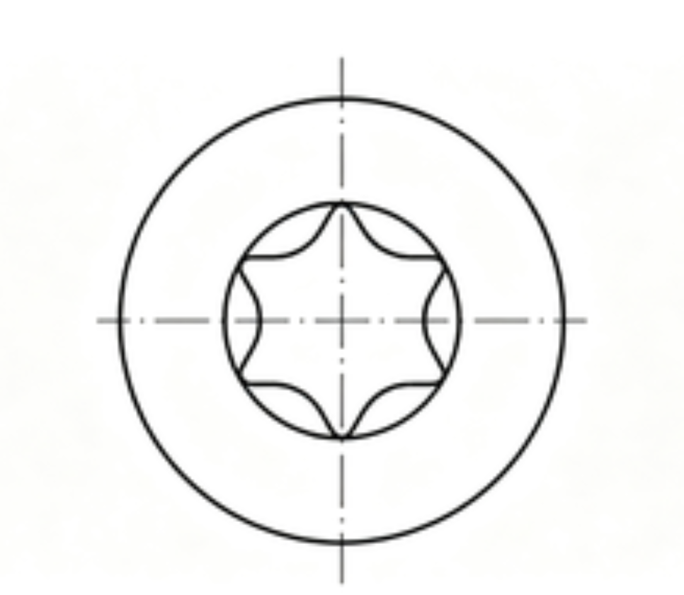 Torx six-lobe geometry
Not sure which head and drive?
Send the assembly section and the driver specification. We will recommend a combination that fits the stack and works on your line.