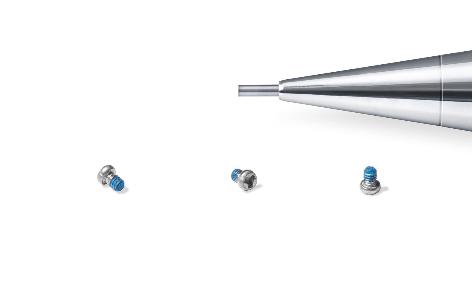
Micro Screws · M0.8 – M6
Precoated Screws
Screws with a factory-applied locking or sealing element, so the assembly line receives a ready-to-drive fastener with no liquid adhesive and no cure time.
Nylon patchMicro-encapsulated3M tape
Micro Screws
M0.5 to M6 machine screws for threaded metal and plastic assemblies
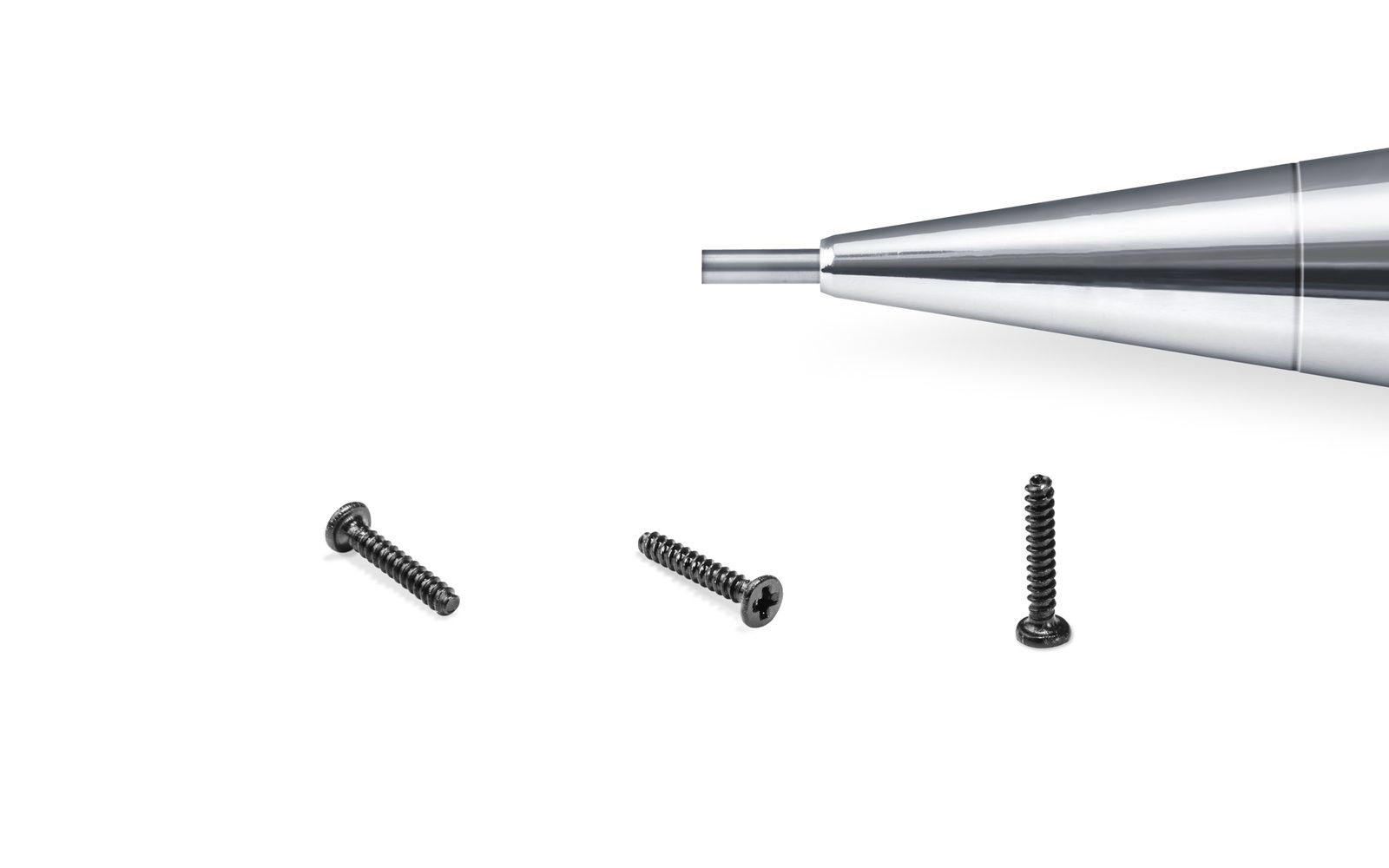 M0.5 – M6 · Micro Screws
Overview
Machine thread micro screws are the backbone of miniature assemblies. They join metal inserts, tapped housings and stacked components where the thread must engage smoothly, hold preload and survive repeated service. At diameters below M2, a few micrometres of thread error is enough to cause cross-threading, cam-out or a dropped clamp load — so the process window has to be controlled from the wire rod onward.
We produce machine thread micro screws by cold heading, then roll the thread rather than cut it. Rolling reforms the grain structure along the thread flank instead of severing it, which raises fatigue strength and leaves a smoother flank finish. Threads are gauged to ISO 68-1 / ISO 965-2 Class 6g, with 6f available for applications that need a tighter fit. Every lot is optically sorted for head cracks, incomplete threads and dimension drift before packing.
Diameter range
M0.5 – M6
Thread standard
ISO 68-1 / ISO 965-2, Class 6g (6f on request)
Thread form
Rolled, coarse and fine pitch
Length range
1.2 mm – 60 mm
Length tolerance
±0.05 mm (< 3 mm) / ±0.10 mm (3 – 10 mm)
Head diameter tolerance
±0.03 mm
Design intent
Six engineering decisions that separate a micro fastener that works from one that merely fits the drawing.
Thread rolling follows the grain flow of the wire, improving fatigue life and producing a flank finish that engages cleanly in tapped aluminium and brass.
Head-to-shank concentricity is held within 0.03 mm on micro sizes, so automated drivers pick the screw cleanly and torque is applied without wobble.
Punch geometry is dressed on a fixed interval and verified by gauge and vision, preventing the burrs that cause bit cam-out at M1 and below.
Short lengths down to 1.2 mm are held at ±0.05 mm, which matters when a screw must sit flush inside a 1.5 mm wall section.
Austenitic stainless for corrosion, martensitic stainless for hardness, alloy steel for 8.8–12.9 property classes, brass and titanium where weight or conductivity matters.
Each carton carries a lot code linked to wire heat number, forging date, heat treatment batch, coating batch and inspection record.
Technical data
Reference data for design and sourcing. For a specific part, the drawing governs — these tables are the starting point for a joint review.
| Size | Pitch (mm) | Tapping drill Ø (mm) | Close fit | Typical drive | Max torque (N·m, 8.8) |
|---|---|---|---|---|---|
| M0.5 | 0.125 | 0.35 | 0.45 | Slotted 0.8 | 0.02 |
| M0.6 | 0.15 | 0.45 | 0.55 | Phillips 000 | 0.03 |
| M0.8 | 0.20 | 0.65 | 0.75 | Phillips 000 / T1 | 0.06 |
| M1.0 | 0.25 | 0.75 | 0.85 | Phillips 000 / T2 | 0.10 |
| M1.2 | 0.25 | 0.95 | 1.05 | Phillips 0 / T3 | 0.15 |
| M1.4 | 0.30 | 1.10 | 1.20 | Phillips 0 / T3 | 0.22 |
| M1.6 | 0.35 | 1.25 | 1.35 | Phillips 0 / T4 | 0.35 |
| M2.0 | 0.40 | 1.60 | 1.70 | Phillips 1 / T5 | 0.60 |
| M2.5 | 0.45 | 2.05 | 2.10 | Phillips 1 / T6 | 1.20 |
| M3.0 | 0.50 | 2.50 | 2.60 | Phillips 1 / T8 | 2.10 |
| M4.0 | 0.70 | 3.30 | 3.40 | Phillips 2 / T20 | 4.80 |
| M5.0 | 0.80 | 4.20 | 4.30 | Phillips 2 / T25 | 9.50 |
| M6.0 | 1.00 | 5.00 | 5.20 | Phillips 3 / T30 | 16.5 |
Values are typical for the stated material and finish. Actual performance depends on the mating material, engagement length and assembly torque. Confirm with a sample test before design freeze.
Options
Mix these within one part number family. Where a combination is not manufacturable at your tolerance, we will say so at quotation rather than after the first lot.
Where it is used
Representative positions rather than an exhaustive list. Many of our parts are designed for one specific assembly and never appear in a catalogue.
| Assembly | Typical use |
|---|---|
| Smartphone mid-frames | M1.0–M1.4 pan head screws joining display brackets to the chassis |
| Notebook hinges | M1.6–M2.0 flat head screws with threadlocker pre-applied |
| Camera modules | M1.2 low-head screws keeping the module stack under 0.8 mm |
| Robot finger joints | M1.4–M2.0 high-strength screws retaining pulley and linkage plates |
| PCB hardware | M2.0–M3.0 screws into brass inserts and standoffs |
| Wearable cases | M0.8–M1.2 stainless screws with sealed heads |
Quality control
Inspection is not a final gate. It is a set of checks placed where a process can actually drift, with the result recorded against the lot code.
01
Thread ring gauge, GO / NO-GO, 100% sampling per lot
02
Head diameter and height, optical comparator
03
Length, contact-type micrometer with low force
04
Concentricity, vision system
05
Drive recess depth and burr, vision and pin gauge
06
Hardness, Vickers micro-hardness (HV 0.3)
07
Salt spray, neutral 5% NaCl, 35 °C
08
Hydrogen embrittlement relief verification for high-strength steel
Questions
The questions our engineers answer most often on this product family.
Related products
These families are frequently used in the same assembly, or as an alternative when the joint requirement changes.
Micro Screws · M0.8 – M6
Screws with a factory-applied locking or sealing element, so the assembly line receives a ready-to-drive fastener with no liquid adhesive and no cure time.
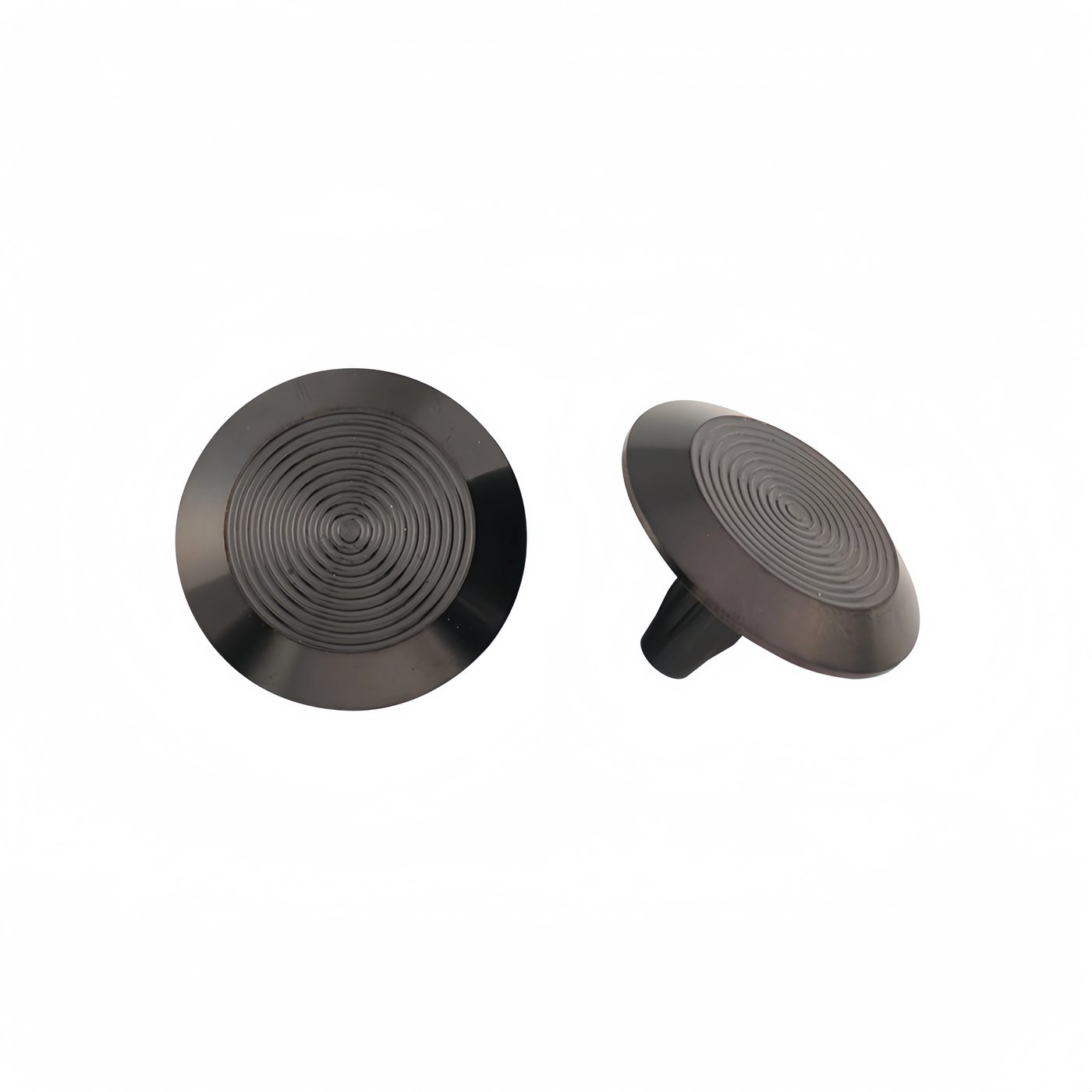
Micro Screws · M0.8 – M6
Physical vapour deposition coatings that add 2–5 µm of hard ceramic film — for driver wear resistance, low friction and decorative black or gold finishes.
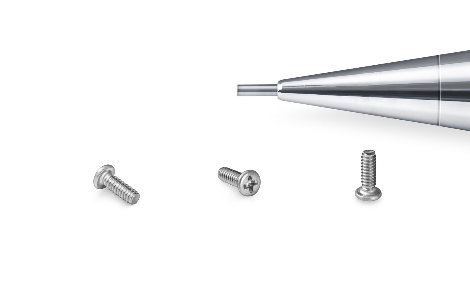
Micro Screws · M0.6 – M4
Self-tapping micro screws from M0.6 to M4 with controlled point geometry, engineered to form clean threads in engineering plastics without cracking the boss.
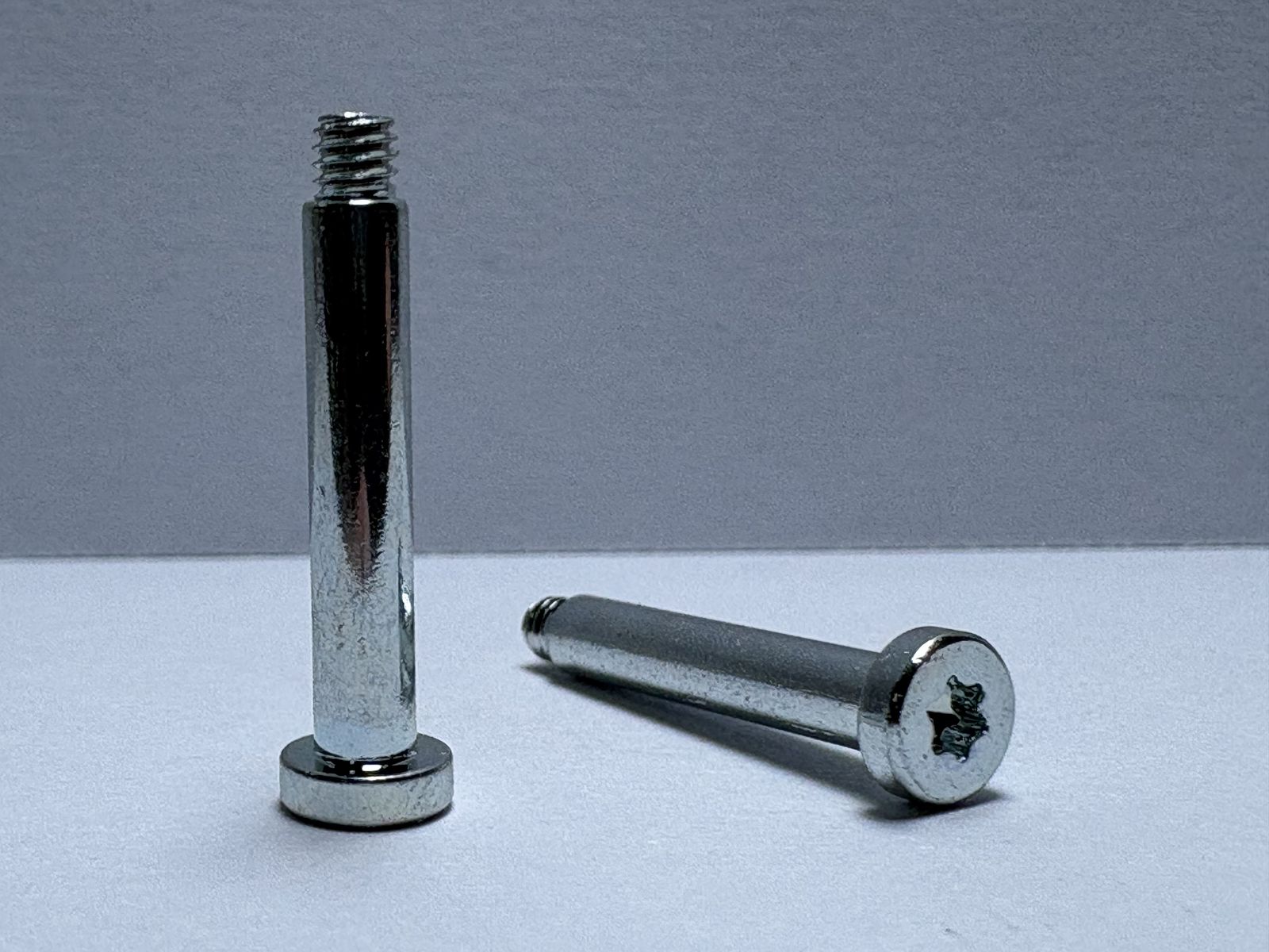
Precision Components · Ø1.0 – Ø10 mm
Precision shoulder screws, dowel pins and stepped pins ground to h9 for pivot, locating and alignment duties in miniature mechanisms.
Send a drawing or 3D model with the mating material and finish requirement. We reply with a process route, tolerance review and price — usually within two working days.