
Capability
Thread Rolling
Threads formed by pressure, not cut by removal
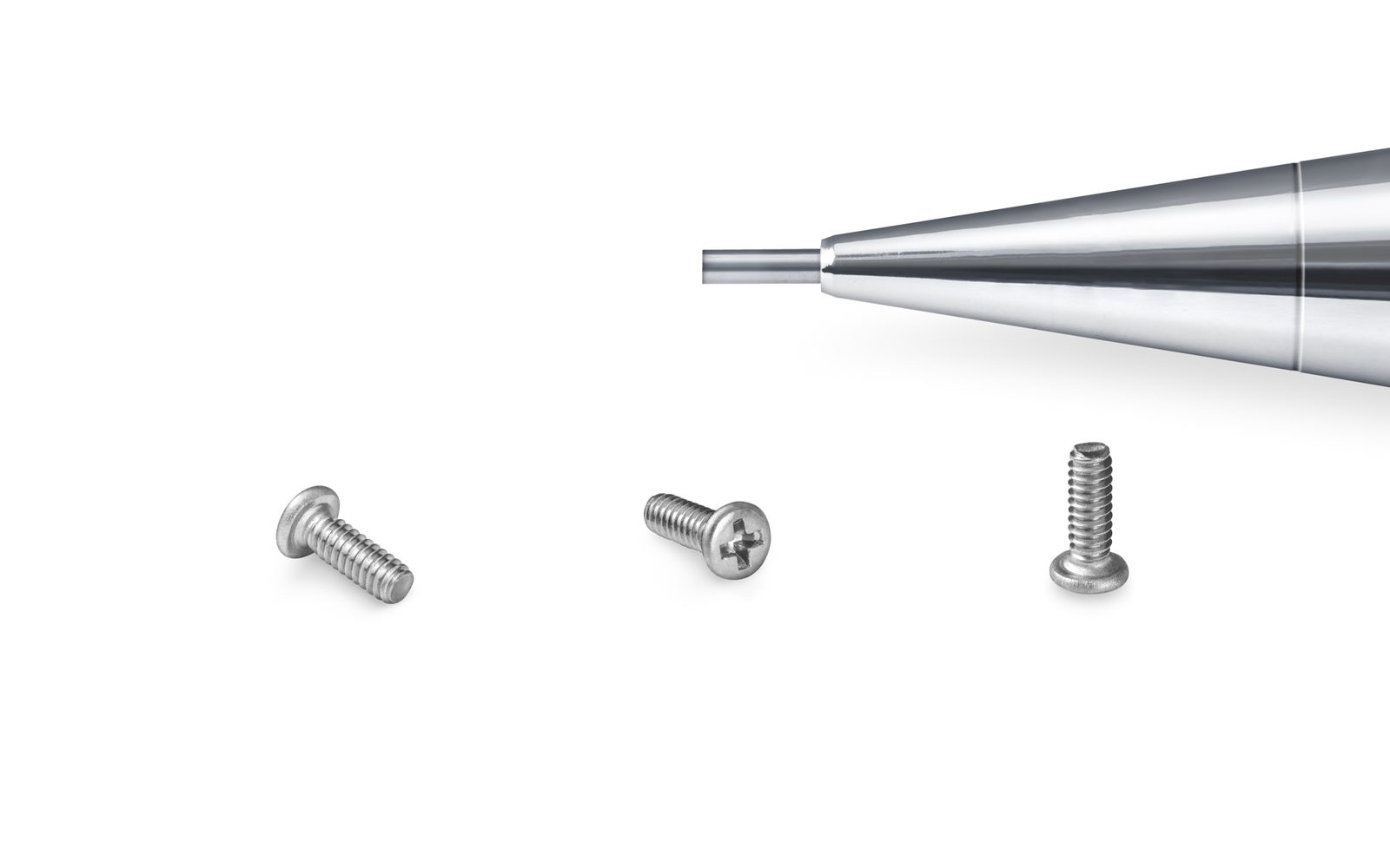 Thread Rolling · Bekasi plant
Process overview
Threads formed by pressure, not cut by removal
A cut thread is a series of small cuts through the material, and every cut leaves a notch at the root. A rolled thread is formed by pressing the blank between dies, so the material is displaced rather than removed — the grain runs along the thread profile instead of being severed across it.
The practical consequences are a stronger thread, a smoother flank, no chip waste and a more consistent pitch. For a micro screw this matters more than for a large bolt, because the thread is a much larger fraction of the part: at M1.0 there is very little material at the root, so anything that improves the root condition has a disproportionate effect on how the screw performs.
Step by step
How the process runs
Each step has a defined control point. The sequence is not arbitrary — changing it changes the result.
Blank preparation
The formed blank is brought to the diameter the rolling dies are set for, so that the thread is displaced to the correct major diameter.
Die set-up
Flat or cylindrical dies are set to the pitch and flank angle of the thread specification.
Rolling
The blank is rolled between the dies and the material flows into the thread form, with the grain following the flank.
Gauging
Threads are checked with GO / NO-GO ring gauges and the major diameter is measured against the drawing.
Post-rolling route
Parts go to heat treatment or coating as specified, with thread gauging repeated after coating where the finish affects the fit.
Specification
Process window and capability
The numbers below define what the process can hold repeatably. They are not laboratory bests.
Process
Thread rolling — material displaced, not cut
Grain structure
Continuous along the thread flank; no severed grain at the root
Surface
Smoother flank than a cut thread
Waste
No chip production
Thread forms
Machine thread coarse and fine pitch; self-tapping forms
Verification
GO / NO-GO ring gauge and major diameter measurement
Re-gauging
Repeated after coating where the finish affects the fit
Equipment
What the line is built on
Capacity figures are per machine and assume a standard part. Complex geometry reduces throughput.
| Equipment | Specification |
|---|---|
| Flat die thread rolling | Thread forming between reciprocating flat dies |
| Cylindrical die rolling | Thread forming between rotating cylindrical dies |
| Thread ring gauges | GO / NO-GO verification per lot |
Process control
What is checked, and when
A control that is not recorded is not a control. Each item below generates a record linked to the lot code, retained for the programme duration.
01
Blank diameter checked before rolling
02
Die condition and set-up verified at start of run
03
GO / NO-GO ring gauge per lot
04
Major diameter and pitch measurement
05
Thread length and runout against drawing
06
Re-gauge after plating or coating
Questions
Thread Rolling FAQ
Practical questions from sourcing and engineering teams.
Is a rolled thread always better than a cut thread?
Does rolling change the thread dimensions?
Why re-gauge after coating?
Can self-tapping threads be rolled?
Related capabilities
What happens before and after
These processes are usually sequenced with the one above.
Capability
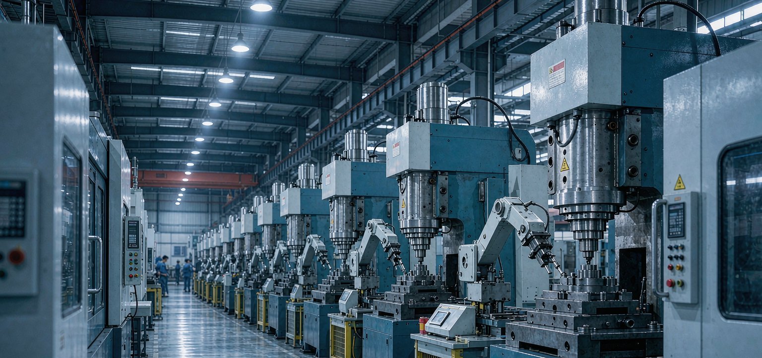
Cold Forging
Single- and multi-station cold heading forms the screw from wire, so the grain follows the part contour and no material is machined away.
Capability
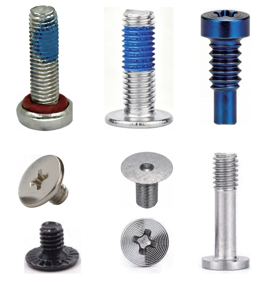
Tooling & Die Shop
Heading dies and punches are designed and built in-house, so geometry can be changed during development instead of waiting for an outside toolmaker.
Capability
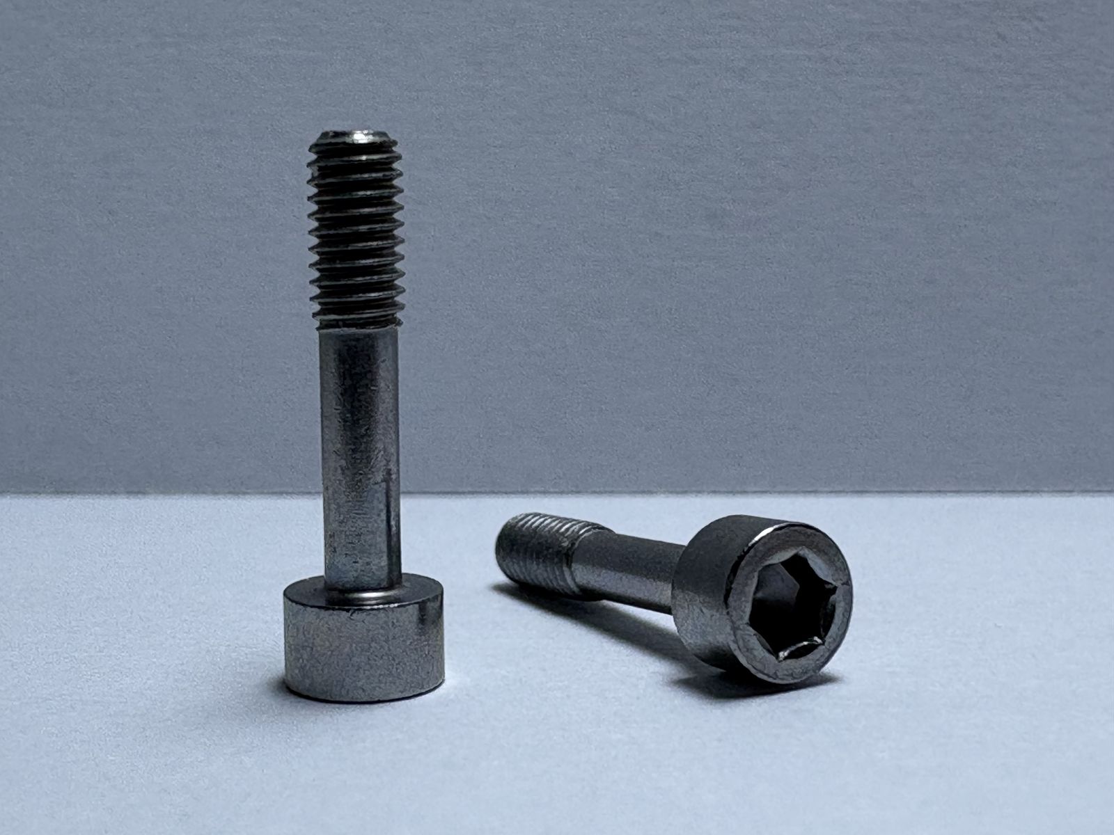
Heat Treatment
Hardening, tempering and case hardening set the balance between a wear-resistant surface and a core that will not fracture — with hydrogen relief where plating demands it.
Need thread rolling for your part?
Send the drawing and the annual volume. We will confirm feasibility, tolerance and lead time in the quotation.