Engineering guide
Torque & preload guide
At M1 the difference between a joint that holds and one that strips is often 0.04 N·m. This guide covers the calculation, the friction data behind it, and how to verify what you actually applied.
The calculation
Two equations, one assumption
Torque is converted into clamp load through friction. That is the whole model — and the friction coefficient is where most of the uncertainty lives.
Preload
F = σ × As
σ is the target stress (typically 0.6–0.75 × proof strength), As is the thread stress area.
Torque
T = K × F × d
K is the nut factor (friction), F the preload in newtons, d the nominal diameter in metres.
As = 2.07 mm², proof strength ≈ 640 MPa, target 70% → F = 0.7 × 640 × 2.07 ≈ 930 N.
With K = 0.15, T = 0.15 × 930 × 0.002 = 0.28 N·m. With K = 0.22 (dry zinc), the same torque produces only 630 N — a 32% loss of clamp load from friction alone.
Rule of thumb
If you cannot measure K, assume ±25% scatter
An unmeasured joint does not have a preload — it has a preload range. For non-critical joints that is acceptable. For a sealed, thermal or safety-relevant joint, measure K with a torque-tension test on the actual parts and finish.
Our laboratory runs torque-tension to ISO 16047.
Ask for a joint test with your parts.
Friction
Nut factor by joint condition
K is not a material constant. It depends on the finish, the lubricant and the surface roughness of both threads. The scatter column matters as much as the mean.
| Joint condition | K factor | Clamp load scatter | When to use |
|---|---|---|---|
| As-received, plain steel | 0.20 | ±25% | General estimation only |
| Zinc plated, dry | 0.22 | ±25% | Low-criticality joints |
| Zinc-nickel with lubricant | 0.14 – 0.16 | ±12% | Controlled preload, automotive |
| Black oxide, lightly oiled | 0.18 – 0.21 | ±18% | Internal cosmetic joints |
| PVD DLC | 0.10 – 0.13 | ±10% | Low friction, high-cycle |
| Stainless, passivated, dry | 0.24 – 0.30 | ±30% | Galling-prone; use anti-seize |
| Molybdenum disulphide paste | 0.12 – 0.15 | ±12% | High preload, controlled |
| Wax / dry-film lubricant | 0.13 – 0.17 | ±15% | Clean assembly, no liquid |
Scatter values are indicative for production parts. A controlled finish with a specified lubricant can hold ±12%; an unspecified dry joint can exceed ±30%.
Reference data
Stress area and recommended torque
Calculated at 70% of proof strength with K = 0.20 for 8.8 and 12.9, and K = 0.24 for A2-70 stainless. Use these as a starting point, then verify on the actual joint.
| Size | Stress area As (mm²) | 8.8 preload (N) | 8.8 torque (N·m) | 12.9 torque (N·m) | A2-70 torque (N·m) |
|---|---|---|---|---|---|
| M1.0 | 0.46 | 210 | 0.04 | 0.06 | 0.03 |
| M1.2 | 0.65 | 290 | 0.07 | 0.10 | 0.05 |
| M1.4 | 0.88 | 395 | 0.11 | 0.16 | 0.07 |
| M1.6 | 1.27 | 570 | 0.18 | 0.27 | 0.12 |
| M2.0 | 2.07 | 930 | 0.37 | 0.55 | 0.24 |
| M2.5 | 3.39 | 1,520 | 0.76 | 1.14 | 0.49 |
| M3.0 | 5.03 | 2,250 | 1.35 | 2.03 | 0.88 |
| M4.0 | 8.78 | 3,930 | 3.15 | 4.72 | 2.04 |
| M5.0 | 14.2 | 6,360 | 6.36 | 9.54 | 4.13 |
| M6.0 | 20.1 | 9,000 | 10.8 | 16.2 | 7.02 |
Values are for unlubricated, as-received parts. A lubricated or coated joint with lower K will need proportionally lower torque for the same preload — do not apply these figures to a DLC-coated screw.
Upper bound
Strip torque in the mating material
The joint fails at whichever is weaker: the screw or the female thread. In aluminium and brass the female thread usually governs, so the torque target must sit below it.
| Size | Brass insert (N·m) | Aluminium 2 mm wall (N·m) | Steel tapped (N·m) | Plastic boss (N·m) |
|---|---|---|---|---|
| M1.0 | 0.18 | 0.11 | 0.25 | 0.09 |
| M1.2 | 0.26 | 0.16 | 0.36 | 0.13 |
| M1.4 | 0.36 | 0.22 | 0.50 | 0.18 |
| M1.6 | 0.50 | 0.31 | 0.70 | 0.26 |
| M2.0 | 0.90 | 0.55 | 1.25 | 0.45 |
| M2.5 | 1.60 | 0.95 | 2.20 | 0.78 |
| M3.0 | 2.60 | 1.55 | 3.60 | 1.25 |
| M4.0 | 5.50 | 3.30 | 7.60 | 2.70 |
Strip torque values are typical for the stated material and engagement length. They vary with engagement, wall thickness and alloy condition. Measure in the actual mating part before setting a torque specification.
Setting a window
From calculation to a line specification
01
Define the functional clamp load
Sealing, thermal contact or vibration resistance each imply a minimum preload. Start there, not from a torque table.
02
Measure K on the actual parts
Ten assemblies, torque-tension test, record the preload scatter. This gives the K range, not a single number.
03
Measure strip torque in the mating part
Ten drives into the real material. Take the lower bound and apply a safety factor of at least 1.4.
04
Set the target inside both bounds
The driver's upper tolerance must stay below 70% of strip torque; the lower tolerance must still meet the functional clamp load.
05
Verify on the line, at production speed
A hand driver is not a production tool. Check torque with the actual driver, at cycle rate, on the first three parts of every lot.
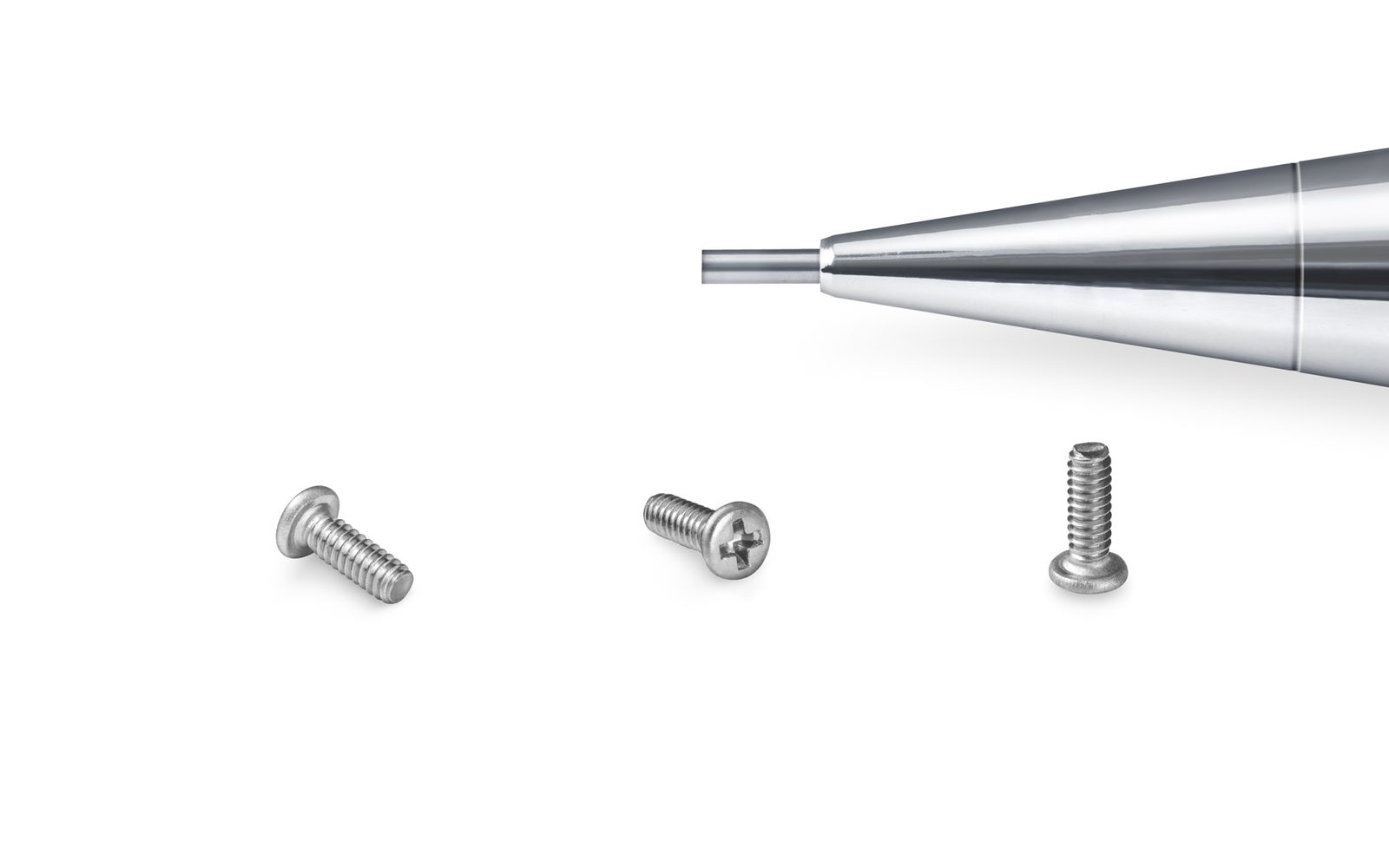 Micro screws · torque-tension test samples
Questions
Torque FAQ
Common questions from design and process engineers.
Which formula should I use for preload?
Why is my calculated torque different from the supplier’s recommendation?
Is a higher property class always better?
How do I verify torque on the line?
What causes a screw to break under the head?
Ask for a torque-tension test
Send a sample of the screw and the mating part. We will measure K, strip torque and the preload range, and recommend a line specification.