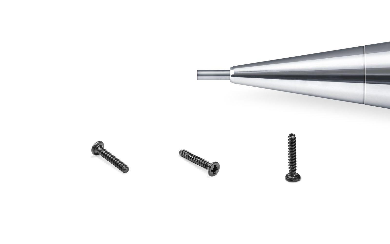
Micro Screws · M0.5 – M6
Machine Thread Micro Screws
Precision machine screws from M0.5 to M6 with rolled Class 6g threads, tight head concentricity and clean drive recesses for automated driving.
Precision Components
M1 to M4 threaded standoffs, spacers and PCB hardware
M1 – M4 · Precision Components Overview
Standoffs set the distance between two boards, a board and a chassis, or a panel and a frame. In a multi-board stack the accumulated error of four standoffs decides whether connectors mate without stress, so the length tolerance matters as much as the thread. A standoff that is 0.15 mm long tilts the board and loads one corner of a fine-pitch connector.
We machine standoffs from brass, stainless steel and aluminium on automatic lathes, with hex across-flats from 2.5 mm and lengths from 2 mm. Female-female, male-female and male-male configurations are all available, with through-thread or blind-thread options. Lengths are held at ±0.05 mm and the two end faces are square to the thread within 0.03 mm, which is what actually keeps a stack parallel.
Thread range
M1 – M4 (M2.5 and M3 most common)
Configurations
Female-female, male-female, male-male
Body shapes
Hex, round, square
Hex across-flats
2.5 / 3.0 / 4.0 / 5.0 / 5.5 / 6.0 mm
Length range
2 – 60 mm
Length tolerance
±0.05 mm
Design intent
Six engineering decisions that separate a micro fastener that works from one that merely fits the drawing.
Face-to-face length is ground or faced in a second operation, so a four-standoff stack stays parallel instead of loading one corner.
End faces are square to the thread axis within 0.03 mm, preventing the tilt that misaligns fine-pitch board connectors.
Small across-flats sizes suit densely populated boards where a standard 5.5 mm hex will not fit between components.
Through-thread for pass-through fixing, blind-thread where the thread must not breach the top face or where debris must be excluded.
Brass and aluminium for grounding, anodised aluminium or nylon for isolation between noisy and sensitive grounds.
Standoffs can be supplied with a swage collar or press-fit knurl for permanent installation into a chassis panel.
Technical data
Reference data for design and sourcing. For a specific part, the drawing governs — these tables are the starting point for a joint review.
| Thread | Hex A/F (mm) | Round Ø (mm) | Length range (mm) | Typical board pitch | Material |
|---|---|---|---|---|---|
| M1.0 | 2.5 | 2.0 | 2 – 12 | 0.8 mm | Brass |
| M1.2 | 3.0 | 2.4 | 3 – 15 | 1.0 mm | Brass |
| M1.6 | 3.0 | 2.8 | 3 – 20 | 1.2 mm | Brass / SS |
| M2.0 | 4.0 | 3.5 | 4 – 30 | 1.6 mm | Brass / SS |
| M2.5 | 5.0 | 4.0 | 4 – 40 | 2.0 mm | Brass / Al |
| M3.0 | 5.5 | 5.0 | 5 – 50 | 2.5 mm | Brass / Al |
| M4.0 | 6.0 | 6.0 | 6 – 60 | 3.0 mm | Brass / Al |
Values are typical for the stated material and finish. Actual performance depends on the mating material, engagement length and assembly torque. Confirm with a sample test before design freeze.
Options
Mix these within one part number family. Where a combination is not manufacturable at your tolerance, we will say so at quotation rather than after the first lot.
Where it is used
Representative positions rather than an exhaustive list. Many of our parts are designed for one specific assembly and never appear in a catalogue.
| Assembly | Typical use |
|---|---|
| Multi-board PCB stacks | M2.0–M3.0 brass standoffs setting 2.5 mm board pitch |
| GPU and accelerator cards | M3.0 standoffs bracing heavy heatsink assemblies |
| Robot control boards | M2.5 standoffs with vibration-resistant threadlocker |
| Panel-mount connectors | M2.0 male-female standoffs setting D-sub height |
| Optical benches | M4.0 aluminium spacers with ±0.02 mm length |
| Wearable electronics | M1.0 micro standoffs in 0.6 mm board stacks |
Quality control
Inspection is not a final gate. It is a set of checks placed where a process can actually drift, with the result recorded against the lot code.
01
Length, face to face, 100% on critical stacks
02
Face squareness to thread axis
03
Thread gauge, GO / NO-GO both ends
04
Across-flats and roundness
05
Concentricity of male thread to body
06
Plating thickness, XRF
07
Contact resistance where grounding is specified
08
Salt spray for plated brass
Questions
The questions our engineers answer most often on this product family.
Related products
These families are frequently used in the same assembly, or as an alternative when the joint requirement changes.
Micro Screws · M0.5 – M6
Precision machine screws from M0.5 to M6 with rolled Class 6g threads, tight head concentricity and clean drive recesses for automated driving.
Precision Components · Ø1.0 – Ø10 mm
Precision shoulder screws, dowel pins and stepped pins ground to h9 for pivot, locating and alignment duties in miniature mechanisms.
Specialties · 0.05 – 1.5 mm strip
Progressive-die stamped parts from 0.05 to 1.5 mm strip — contacts, spring clips, EMI shields and mounting brackets produced alongside our screw lines.
Precision Components · M2 – M6
Captive panel screws that remain attached to the cover when opened — eliminating lost fasteners in field service, medical and rack-mount equipment.
Send a drawing or 3D model with the mating material and finish requirement. We reply with a process route, tolerance review and price — usually within two working days.